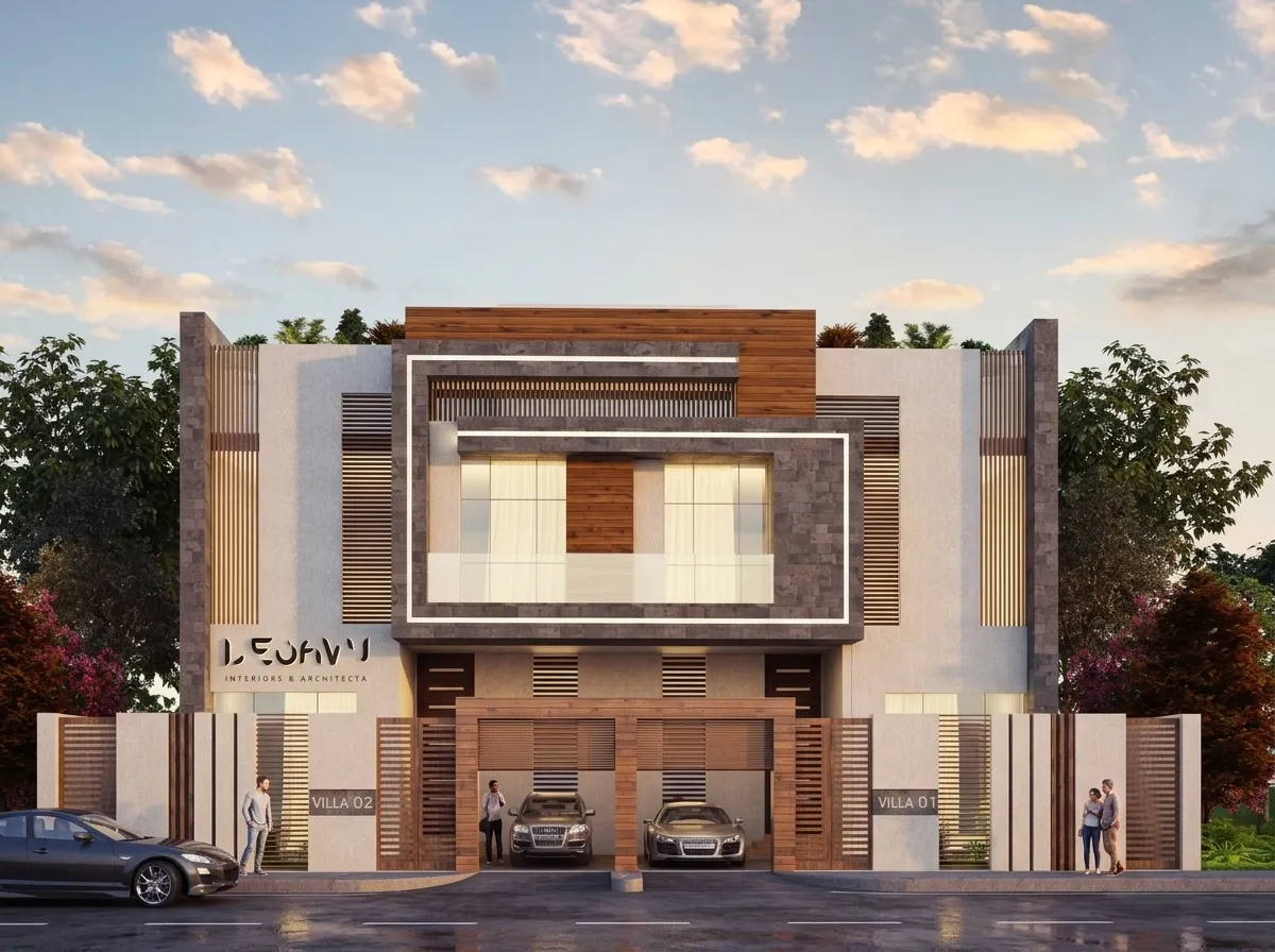
How to Turn a Floor Plan Into a 3D Render
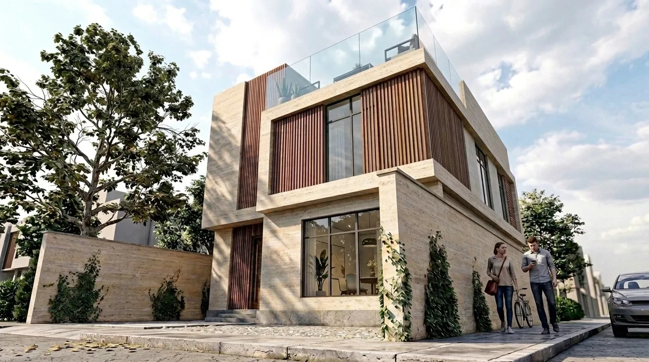
Converting a floor plan into a 3D render has always been a two-stage problem: first you need a model, then you need an image from it. That pipeline typically means rebuilding the plan as geometry in a 3D tool, setting up a camera, assigning materials, and running a render engine. For a quick massing study or a client schematic, the cost of that pipeline is often more than the decision it is meant to support.
AI-assisted floor-plan-to-3D workflows compress the second stage significantly. You do not skip the geometry step, but the render step — taking a view and making it look real — becomes fast enough to iterate.
Why floor plan to 3D is hard
The fundamental difficulty is that a floor plan is a 2D representation of spatial intent. It encodes wall positions, room relationships, and opening locations, but it does not encode height, material, or the quality of light that will enter the space. Going from plan to render means making dozens of inferences, and those inferences compound.
Generic AI tools handle this badly because they treat the plan as a loose reference and fill in the spatial gaps with plausible-looking but arbitrary choices. Walls move. Proportions shift. The result does not match the plan because the model was not constrained to honor it.
The correct approach is to extract the geometry from the plan first, then render from a real camera placed within that geometry. The plan becomes the spatial constraint, not just a mood reference.
Preparing a clean plan
The cleaner the input, the more accurate the extraction. A few practical notes:
- Remove annotation layers. Dimension lines, text, hatch patterns, and furniture symbols add noise. A clean wall outline is a better input than a fully annotated working drawing.
- Check wall closure. Open corners and disconnected wall segments create ambiguities in the geometry. Close them before extraction if possible.
- High contrast. Black walls on a white background read far more reliably than a mid-gray plan on a tinted sheet.
A PDF export from your CAD tool or a clean scan at adequate resolution is usually sufficient. The goal is a file where the wall boundary is unambiguous.
Extracting and vectorizing walls
The extraction step converts the 2D plan image into a set of wall segments with spatial coordinates. This is where the floor plan becomes geometry you can navigate. The vectorized output captures wall positions and connectivity — enough to build a navigable 3D space.
Once walls are extracted, room boundaries are derived from their topology. Openings (doors, windows) are detected from gaps or threshold patterns in the plan. The result is a spatial model, not a photorealistic image, but it is a model with the correct dimensions and relationships of the original plan.
Placing a camera
Camera placement is the most consequential decision in going from a floor plan to a render, because the camera defines what the client sees and what the render communicates.
Consider what the space needs to say:
- An entry sequence is best read from a position just inside the threshold looking toward the main volume.
- A living space often reads better from a corner, capturing two walls and a sense of enclosure.
- A kitchen or utility space benefits from a direct orthographic or near-orthographic shot that reads function clearly.
Eye-level height (roughly 1.5–1.6m) is almost always the right starting point. High vantage angles look spatial but often fail to communicate how a room feels to occupy. For a deeper exploration of how to sequence shots for a client presentation, see Floor Plan to Camera Shot: Walking a Client Through a Space.
Generating the render
Once the camera is placed in the extracted geometry, the render step follows the same pattern as any AI rendering workflow: choose style, lighting direction, time of day, weather, and format. The geometry and camera angle are fixed. The AI reconstructs materials and atmosphere.
A few things that improve results:
- Set time of day deliberately. Interior spaces read very differently under midday sun versus golden hour versus artificial lighting. The choice shapes the mood more than material selection.
- Match the weather to the project type. A residential project often benefits from a warm, clear day. A civic or institutional building can take a more overcast treatment that emphasizes the architecture without weather competing for attention.
- Iterate on atmosphere first, then detail. Run a quick low-resolution pass to confirm the overall light quality, then refine with a higher-output format once the mood reads correctly.
Tips for readable results
The render is a communication tool, not an end in itself. A few habits keep it useful:
- Do not over-furnish the space in source references. Render the architecture first; add furniture context as a second pass if needed.
- Match the camera angle to the decision the client needs to make. If they are choosing between two wall positions, frame the render so both walls are visible.
- Treat the render as illustrative. It shows what the space could feel like, not what it will be. Present it that way.
For a broader look at how AI architectural rendering fits into a design process, see the complete guide to AI architectural rendering.
When you are ready to try the workflow on your own plans, join the Arqina beta and request early access.